A
RGB demodulator for TMS9929A / TMS9928A chip, mostly used on MSX
computers and Colecovision.
This board outputs RGB+CSYNC from the original YPbPr chip channels of
the TMS99 chip. Output from each color channel can be adjusted using a
trimmer. Based on the Universele
interface RGB op MSX1 en SV.328. Mine fixes the emitter follower
transistors of this version. This repository contains the KiCad project
and the Gerber files, the PDF
schematics and the BOM
file.
Features
Each channel can be tuned
Provides audio output pin
Provides 5V output pin (if you want to use it with an RGB Scart
cable for “modern” TVs)
Fits into the MSX composite modulator slot
Extremely cheap!
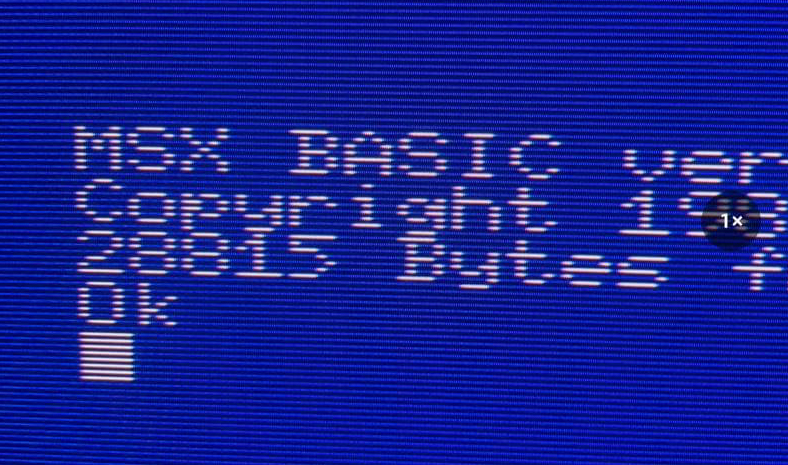
Video
Sample output (photo
taken on BVM 20DU)
VIDEO OUT
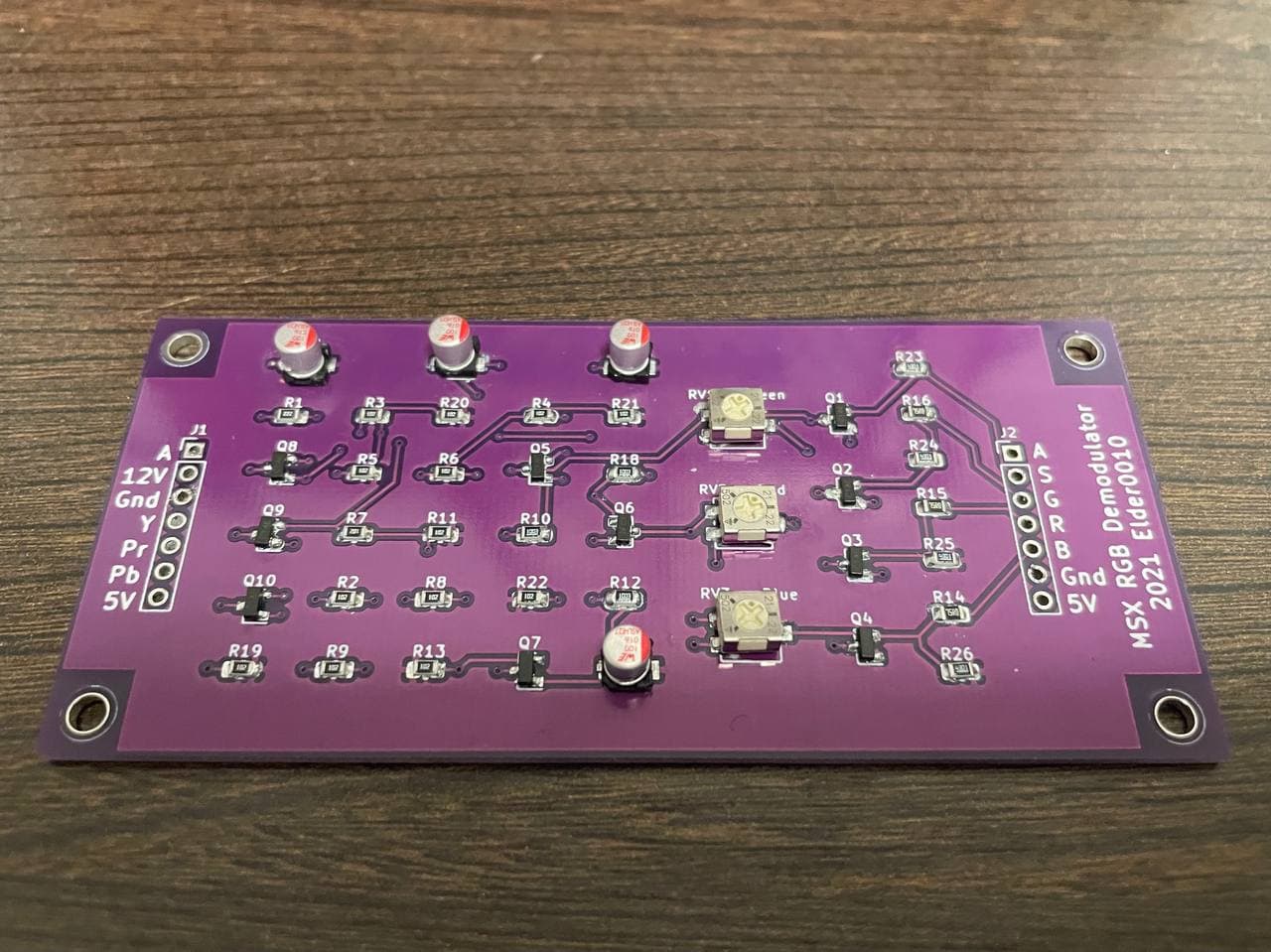
Assembled PCB
PCB
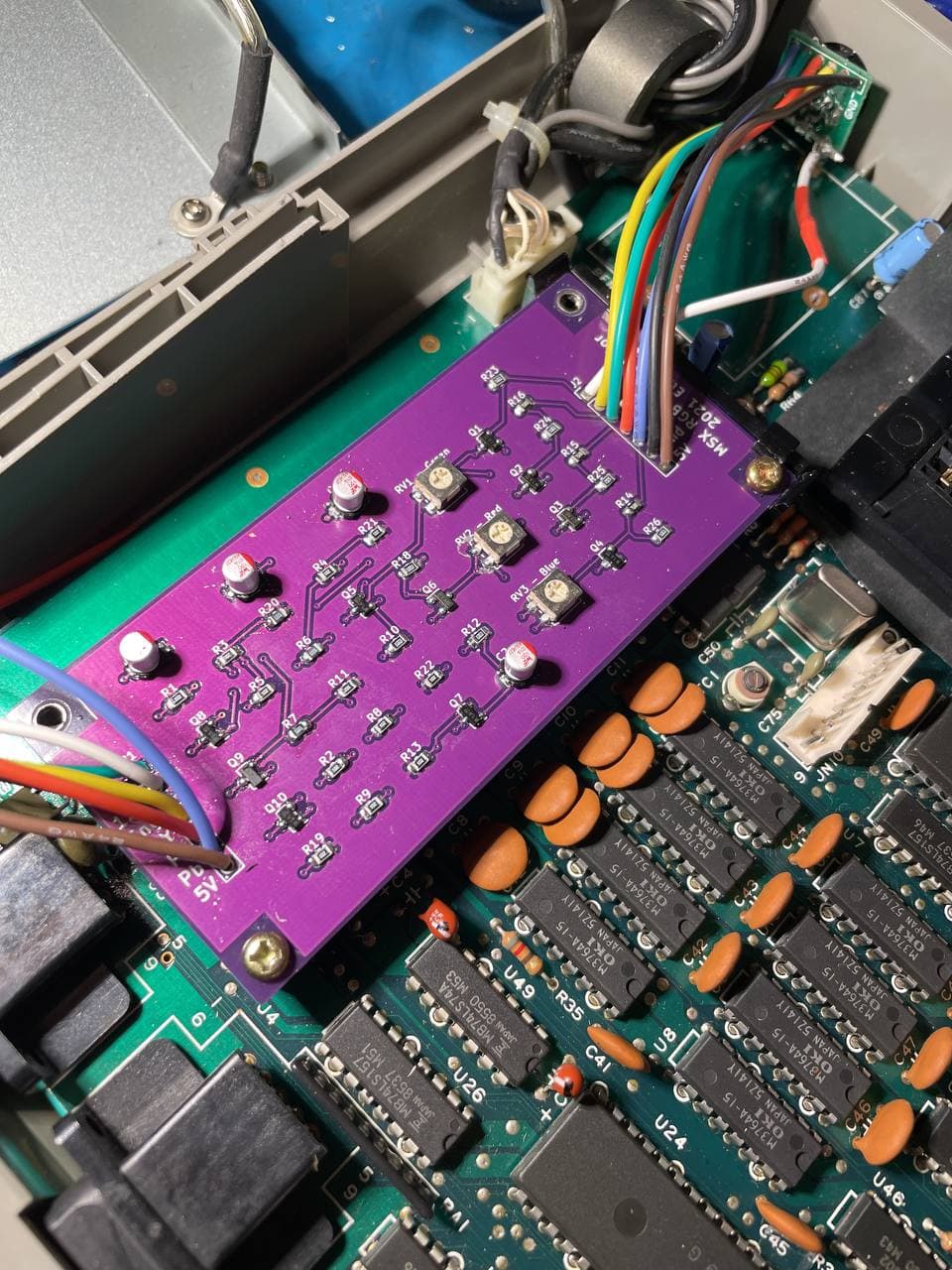
The PCB in a Phonola VG-8020
PCB
How to assemble
Y, Pb, Pr signals must be taken directly from the TMS chip (pin
35,36,38 on TMS9928A or TMS9929A)
Audio is from pin 4 of the AY38910
5V pin is optional: wire it only if you need to connect the computer
to a scart TV.
Removing the original composite modulator (on MSX) is not mandatory
but encouraged: unfortunately it creates noises also on the RGB
interface. Keep in mind that removing the modulator will disable the
composite video and the RF video out of the machine.
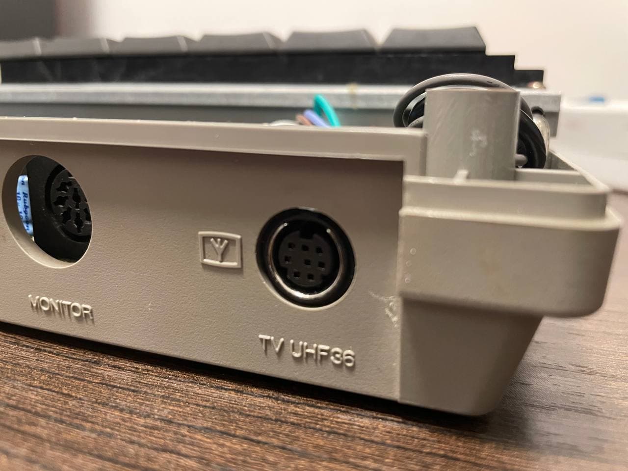
On the Phonola VG8020 I removed the RF modulator to make room for a
8 pin mini din connector. I used the 8pin
Mini DIN to EuroSCART PACKAPUNCH cable for RGB modified consoles.
It’s possible also to desolder the original composite out connector and
use a 8 pin DIN connector to make it compatible with a Sega Genesis 1
SCART cable.
External
view of the mini din connector (RF modulator has been removed)
PCB
Perks
This board provides an RGB output for the TMS9929A / TMS9928A chip.
Although it’s impossible to have 100% correct colours, it’s possible to
obtain a palette very close to the correct one in this way:
Set each RGB trimmer to 0
Turn up a little the RED and GREEN potentiometer until something
visible appears on screen
Turn up the BLUE potentiometer until the background becomes blueish
- keep in mind that the blue channel is the most problematic one because
of the TMS99x non-standard design
Execute the command color 1,1 to set the screen and the text to
black
Notice how the black is blueish, and turn down the BLUE
potentiometer until the background becomes less blueish ;)
Execute the command color 15,4 to restore the screen to the default
colours
Repeat until you get a satisfactory result
adjust the GREEN and the RED potentiometer accordingly
In this way the palette should be close to the original.
Compatibility
This board has been tested with TMS9929A (PAL) chip and TMS9928A
(NTSC).